SpaceWire UK
Specialist providers of VHDL Intellectual Property & Design Services


 icon in the Diagram pane inside the BLOCK DESIGN section.
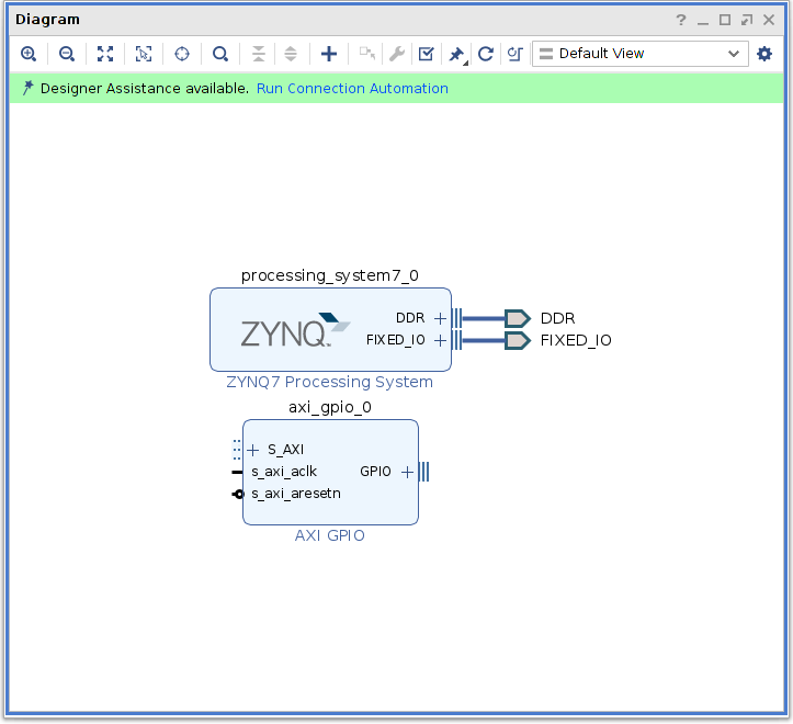
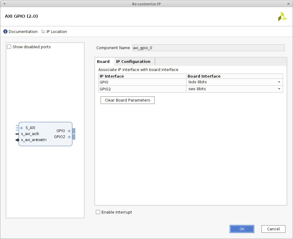
 icon and select AXI GPIO from the menu. The diagram now shows two unconnected IP modules.
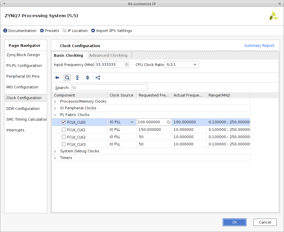
 A fabric clock is required for this design to provide a clock to the GPIO module. To re-enable the FCLK_CLK0 connection select Clock Configuration, expand PL Fabric Clocks and tick FCLK_CLK0.
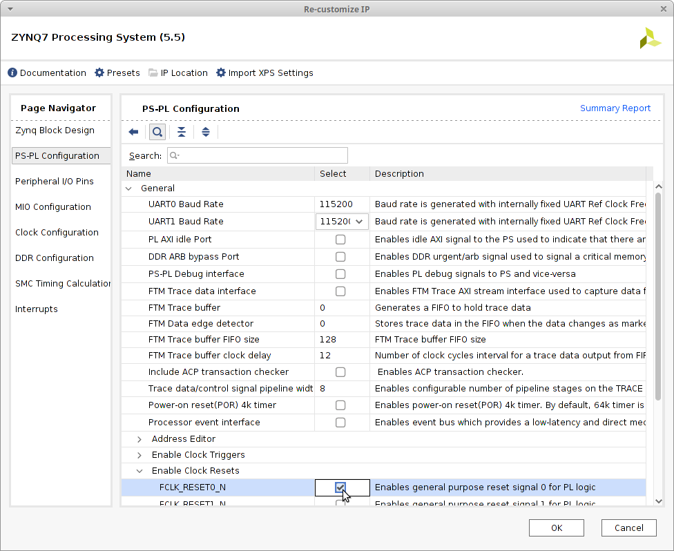
 A fabric reset is required for this design to provide a reset to the GPIO module. To re-enable the FCLK_RESET0_N connection select PL-PS Configuration, expand General, expand Enable Clock Resets and tick FCLK_RESET0_N.
 Click OK to commit the changes.
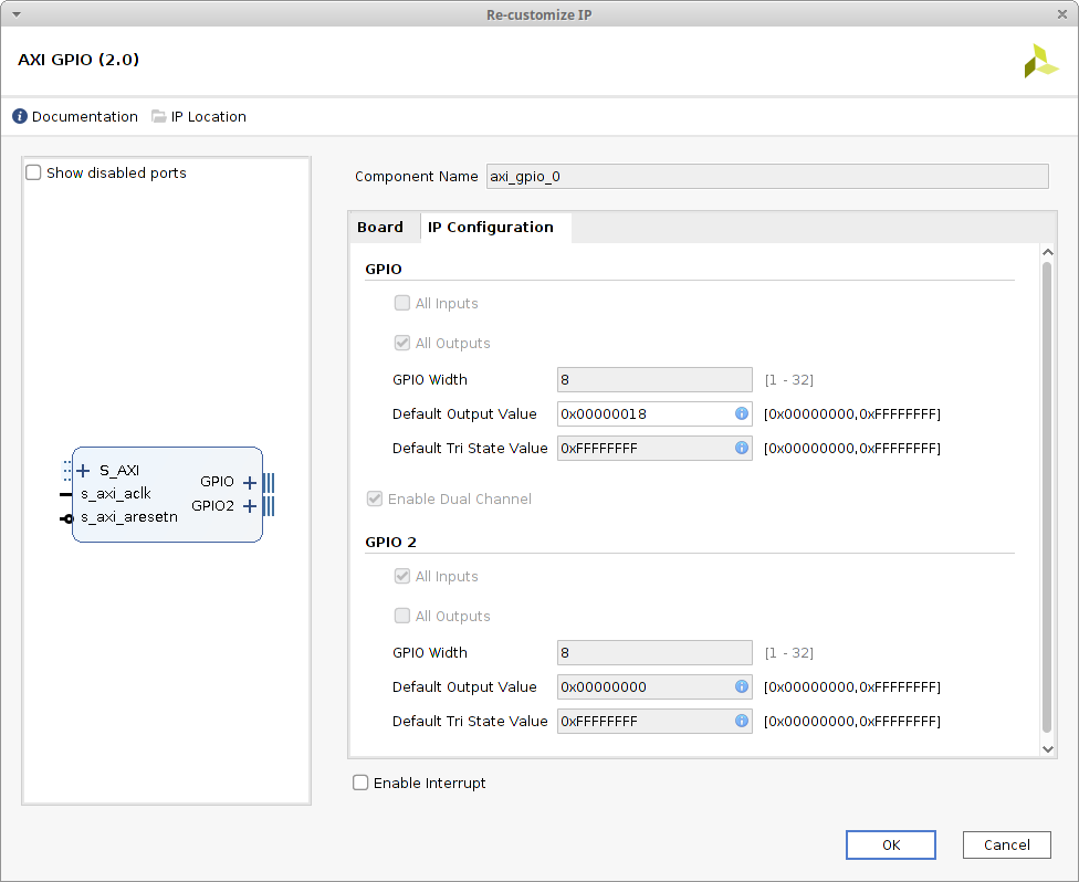
 Add a default value to the GPIO output to illuminate the middle two LED's of the eight. Select the IP Configuration tab and set the Default Output Value within the GPIO section to 0x00000018.
 Click OK to commit the changes.
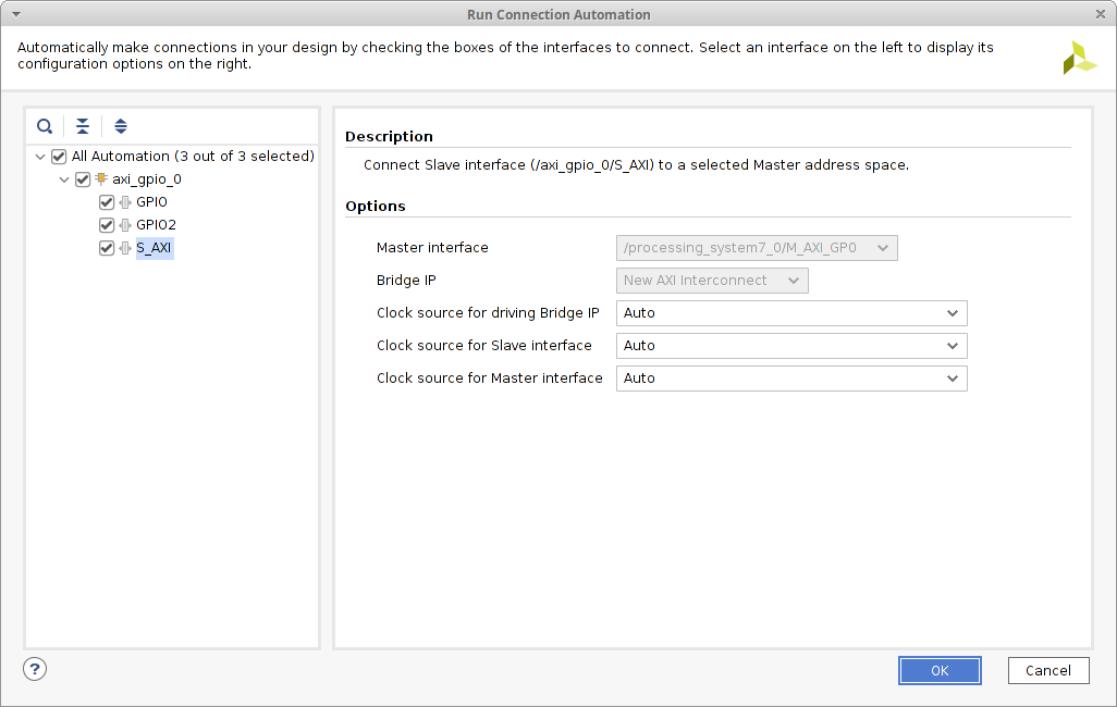
 Review each connection by selected GPIO, GPIO2 & S_AXI respectively. Once reviewed tick All Automation to enable all the suggested connections and then click OK to commit the changes.
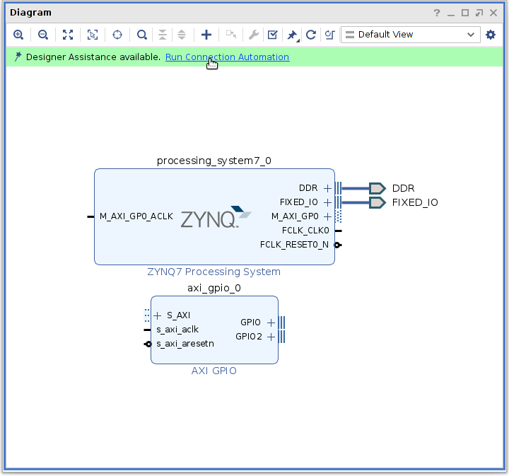
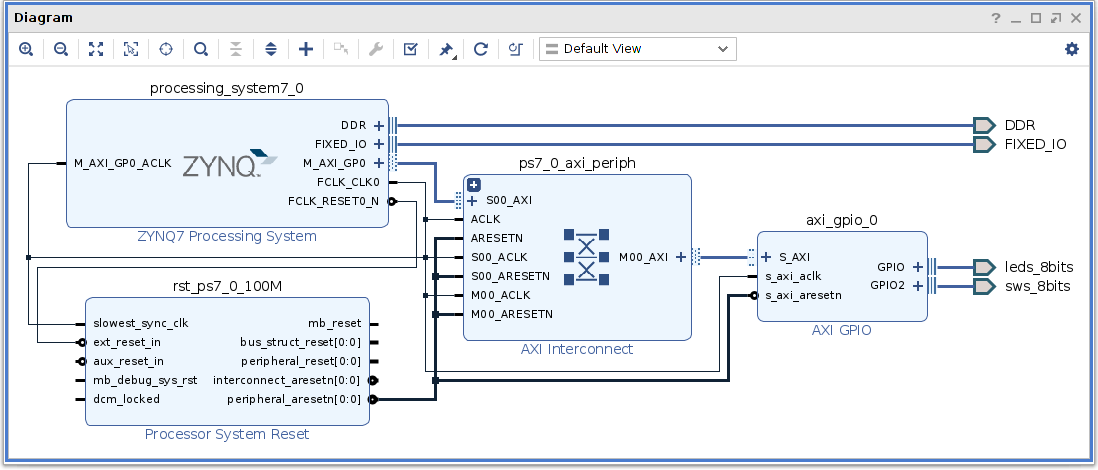
 The extra modules of Processor System Reset & AXI Interconnect are now added to the block design to make connecting up the ZYNQ7 Processing System & AXI GPIO possible. Resize the canvas to obtain a better view of the design and click on the Regenerate Layout
  icon to obtain a better layout.
 icon. Once validated return the floating Diagram pane back to Vivado by clicking on the Dock
  icon.
icon.